Good afternoon, dear readers. Today I want to present to you an article on replacing the MR chain. car VAZ 2106. In this article I will fully describe the process of replacing the motor chain. We will also pay attention to such components as the tensioner and the motor chain damper. This method is suitable for all VAZ (Classic) car models, except for the VAZ 2105 engine, since a belt drive is used there.
When the motor chain wears out, a characteristic sound appears diesel engine (rumble). I think it cannot be confused with anything, and you will immediately understand what needs to be done. If there is nowhere to pull up, the chain begins to sag, and from this there is a noise (roar).
And so, replacing the motor chain.
To carry out this work, we need a partial disassembly of the engine, so we carefully remove the hood, because it will interfere with us. Do not forget to make marks before removing, so that later you do not suffer with its adjustment. I advise you to read the article (How to remove a VAZ engine), it shows how to properly remove the hood.
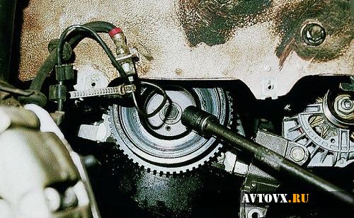
After removing the belt from the pulley, turn on the first gear and press on the brake. At this time, the partner unscrews the nut on the pulley. Prying it off with a wheel wrench or a large screwdriver will easily come off the crankshaft.
You can also use the hand brake, of course, if it holds :).
Now we need to remove the valve cover, for this we remove the air filter, the suction cable from the carburetor and the thrust of the gas pedal. We unscrew the nuts in a circle and remove the cover.
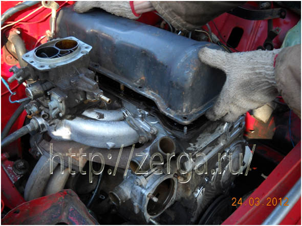
The next step is to remove the front engine cover. To remove it, you need to unscrew the screws and nuts in a circle and, most importantly, do not forget that three bolts fix it to the oil pan.
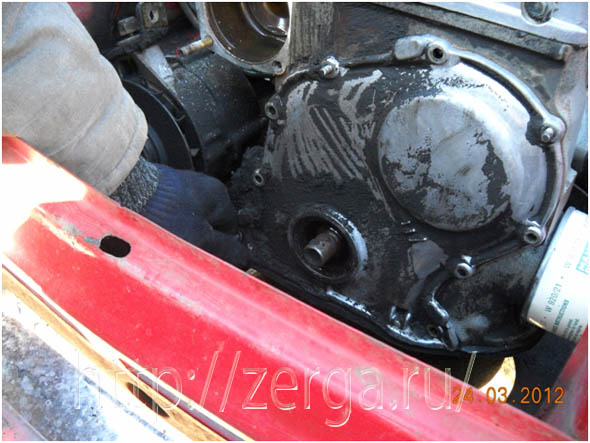
If the cover does not come off, you need to pry it off slightly with a screwdriver, but be careful that the cover cracks.
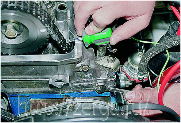
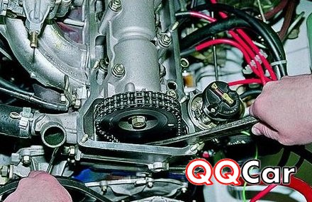
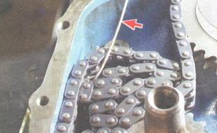
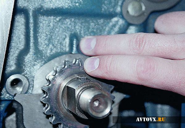
We take out both gears, but the chain itself will not come off. She is not given a restraining finger, which is specially installed so that the chain does not fly off. It also needs to be unscrewed.
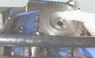
Now we can safely pull out the chain. But that's not all, as they say. We need to see the condition of the tensioner shoe. We remove it.
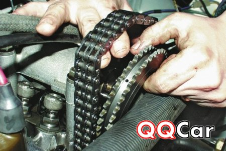
Taking off the shoe, we see that there is a workout on it. Of course, it will still walk, but my advice to you is to replace it with a new one right away, so that you don't go here again.
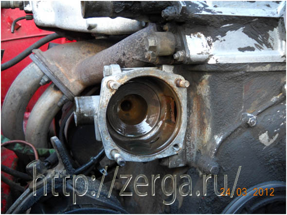
Since we will be installing a new motor chain, if you had an extension cord installed on the tensioner rod (such as collective farm tuning), be sure to remove it. We check the tensioner for serviceability, for this we release the outer nut and press the stem so that it goes inside and tighten the nut. After releasing the nut, the stem should come out under the action of the spring. If the tensioner is working properly, then it can still serve. If not, then the chain tensioner must be replaced.
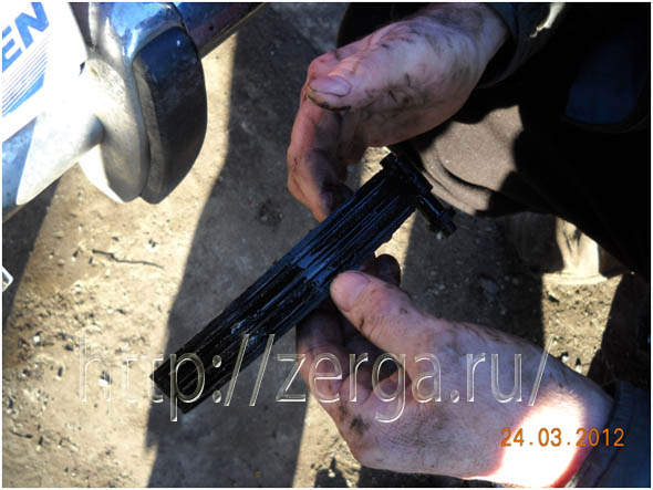
And now it remains for us to replace the chain damper. This part can be torn off during operation, and its remains will fall down the engine. In most cases, the pacifier can be obtained and a new one installed, but there are times when a deplorable situation occurs. So it's better to replace it.
It is fastened to the cylinder head with two screws. To do this, hold it with a screwdriver and unscrew the screws.
Taking more money, we move to the market or store for new parts. We need to buy a motor chain, but be careful, they come in different sizes, so take a look at your previous motor model.
Next, it remains for us to collect everything back. And a couple of tips when assembling. When making adjustments, it is best to install the adjustable gear on the camshaft. I advise you to read the article (Installing the VAZ split gear), you can independently install and adjust the gas distribution mechanism.
When installing the front cover, you need to loosen all the bolts on the oil pan so that the cover is normally installed in its place. And yet, install the pulley and turn the engine a little, and only then screw the cover. Always keep the oil level within the upper level, if it is lower, then the motor chain is poorly lubricated and will fail faster.
That's all, until new publications.
Here you can find other materials on automotive topics
We collect for you a variety of information about the world of cars, both simply interesting as reading material, and useful for carrying out specific work with a car.
In the article below you will find complete data on the gas distribution mechanism of the VAZ 2106, including the device, detailed description maintenance procedures, repair and adjustment work.
Device and maintenance of the gas distribution mechanism of a VAZ 2106 car
The car has deeply entered the life of society and has become the most common means of transportation in the modern world. A big breakthrough in the production of automobiles was the commissioning of the Volga Automobile Plant (VAZ, 1970) and the Kama Automobile Plant (KamAZ, 1976) for the production of trucks.
Currently, there is an intensive improvement of vehicle designs, an increase in their reliability and productivity, a decrease in operating costs, an increase in all types of safety. A necessary condition efficient implementation of plans for the transportation of goods and passengers is the good technical condition of vehicles. To maintain the technical condition of the car in good condition, it is necessary to carry out its maintenance, i.e. a set of organizational and technical measures, the purpose of which is to prevent the occurrence of malfunctions, to reduce the wear of car parts, in which it can carry out transport work with indicators that meet technical requirements. However, even with high-quality maintenance, malfunctions occur, as a result of which it becomes necessary to restore the vehicle's performance or repair.
This thesis examines the maintenance and repair of the gas distribution mechanism of the VAZ-2106 car, as well as the safety of maintenance and repair work.
2. Device and maintenance of the gas distribution mechanism of the VAZ-2106 car.
The engine distribution mechanism is used to regulate the processes of admission of the combustible mixture into the cylinders and the release of exhaust gases from them in accordance with the order of operation of the cylinders adopted for this engine (1-3-4-2), valve timing and speed. The engine of the VAZ-2106 car uses a valve distribution mechanism with an upper single-row inclined valve arrangement and an upper camshaft arrangement (Fig. 1)
Engine valve train:
1-valve; 2-block head; 3-valve sleeve; 4-sealing cap; 5-valve internal spring; 6-valve external spring; 7-biscuit; 8-top plate; 9-lever spring; 10-lever; 11-bearing housing; 12-cam of a camshaft; 13-nut for fastening the bearing housing; 14-valve cover; 15-spherical arm support; 16-support bolt; 17-nut; 18-threaded bushing; 19-support washer; 20-retaining ring; 21-water jacket.
The mechanism consists of a chain drive, a camshaft with a housing, valve drive levers, support adjusting bolts, valves with springs and bushings, and a number of other parts.
The camshaft is driven by a double-row chain with a semi-automatic tensioner and damper (Fig. 2).
Camshaft chain drive:
1-driven camshaft sprocket; 2-row double chain; 3-pacifier; 4-driven shaft sprocket oil pump; 5-drive sprocket; 6-shoe of the tensioner; 7-tensioner.
The cast iron driven camshaft sprocket is cranked by a chain driven by a steel drive sprocket mounted on the toe of the crankshaft. The chain simultaneously rotates a cast iron sprocket attached to the drive shaft of the oil pump, ignition distributor and fuel pump.
A damper fixed to the end of the engine serves to damp the oscillations of the chain. Compensation for backlash that can occur when the chain is pulled out due to its wear is provided by a shoe pressed against it by the tensioner plunger. The tensioner housing is fixedly fixed on the right side of the block head (see appendix). The engine camshaft is cast iron. It is installed in a special bearing housing mounted on the cylinder head. The shaft has five journals, the outer diameters of which are successively reduced to facilitate the installation of the shaft into the housing. The shaft is held against axial movements by a thrust flange placed in the groove of the front bearing journal of the shaft. The working surface of the eight jaws is hardened by currents of high purity, the outer surface of the shaft is phosphated. A through hole is made along the shaft axis, which serves to distribute oil to the journals and cams. The main dimensions of the camshaft and bearing housing are given in the appendix.
The valve levers are used to drive the valves and adjust the valve clearance. When the camshaft rotates, its cam runs onto the lever, forcing it to turn around the spherical support of the bolt head. Descending, the lever presses the valve and opens it. The hairpin spring is designed to create a constant preload at the point where the cam touches the valve. The adjusting bolts are made of steel. The clearances between the cams and levers are changed by rotating the bolts. The bolts are secured with nuts.
The inlet and outlet valves are located in one row in the block head. The inlet valve is made of special steel, and the outlet valve consists of two parts, which are butt-welded. Both valves are nitrided and their stem ends are hardened. In the upper part of the rods there are grooves for crackers. Valve stems move in cast iron guide bushings pressed into the cylinder head. On the outer part of the bushings, an annular groove is cut into which a retaining ring is installed. To prevent excess oil from entering it through the gap between the valve stem and the bore of the bushing, there will be oil slinger caps that are put on the top of the bushing and cover the valve stem. The caps are made of special heat-resistant rubber. Each valve is equipped with two springs supported by their ends from below on steel support washers. And from above on a steel support plate, which is held on the valve stem by steel crackers. The main dimensions of the valves and their sleeves are given in the appendix.
The main malfunctions of the gas distribution mechanism are:
∙ violation of thermal valve clearances,
∙ wear of the chain and drive sprockets,
∙ wear of valve stem seals,
∙ loosening the fastening of the camshaft bearing caps,
∙ loose valve closure due to wear of their heads and seats,
∙ decrease in the elasticity of valve springs,
∙ wear of bearings, journals and camshaft cams.
Violation of adjustments and wear of parts of the gas distribution mechanism is accompanied by increased noise and knocking during engine operation, and a loss of power. Increased pressure smoke and oil consumption. During maintenance of the gas distribution mechanism, a number of works are required: adjusting the valve clearances, checking and installing the valve timing, replacing worn or broken parts.
The camshaft drive chain is tensioned every 10,000 km of vehicle run. Its required value is set automatically by the action of the tensioner, for which it is necessary to loosen its nut and then turn the crankshaft with the starting handle by 1-2 turns. After turning the shaft, the nut must be tightened again to failure.
Checking and adjusting the clearances in the valve drive mechanism is carried out every 10,000 km and in the event that extraneous knocks appear in the valve mechanism. The normal value of the clearance between the lever and the back of the camshaft cam, measured with a feeler gauge on a cold engine, is 0.15 mm for both intake and exhaust valves.
Clearance adjustment is carried out with the valve cover removed in the following sequence:
1. Rotating the crankshaft with the starting handle, align the mark on the camshaft sprocket with the mark on the bearing housing; Loosen the lock nut and turn the head of the adjusting bolt to set a clearance of 0.15 mm at the 3 cylinder inlet valve and 4 cylinder outlet valve.
2. Turn the crankshaft 180 degrees, adjust the clearances at the inlet valve of cylinder 4 and outlet valve of cylinder 2.
3. Turn the crankshaft 180 degrees, adjust the clearances at the inlet valve of cylinder 2 and exhaust valve of cylinder 1.
4. Turn the crankshaft 180 degrees, adjust the clearances at the intake valve of cylinder 1 and exhaust valve of cylinder 3.
When adjusting the gaps, you should use a special gauge 0.15 mm thick and 22 mm wide, which should be pulled out of the gap with a force of 2-3 kgf.
Checking and setting the valve timing is carried out after disassembling the engine or for control. In this case, it is necessary:
1. If the chain is broken, install it so that the plug of the detachable link is directed against the rotation of the chain.
2. Set the piston 1 of the cylinder to the top dead center. In this case, both valves of cylinder 1 are closed, and the mark on the leading sprocket of the distribution drive coincides with the mark on the cylinder block.
3. Make sure that the mark on the driven camshaft sprocket matches the line on the camshaft housing.
4. After finally fixing the driven sprocket, turn the crankshaft several times, adjust the chain tension and check the alignment of the marks.
3. Repair of parts of the gas distribution mechanism.
When repairing and replacing worn parts of the gas distribution mechanism, disassembly is performed in the following order:
1. Remove the cover of the timing mechanism;
2. Turn the crankshaft with the starting handle until the marks on the gear and the camshaft housing are aligned;
3. Loosen the chain tension;
4. Unlock the lock washer under the bolt securing the gear wheel, unscrew the bolt and remove the gear wheel together with the shaft;
5. Loosen the nuts of the camshaft thrust flange, unscrew the nuts securing the bearing housing and remove it together with the shaft;
6. Remove the levers by pressing on its end, resting on the valve stem, turn it around the adjusting bolt;
7. Remove the cylinder head, for which it is necessary to drain the coolant, disconnect the wires from the storage battery, spark plugs and from the coolant temperature gauge sensor. Disconnect the choke cable from the carburetor, remove the spark plugs. Disconnect hoses from carburetor, intake manifold and jacket coolant outlet. Disconnect the starter shield and the front exhaust pipe from the exhaust manifold;
8. Install the cylinder head on the board;
9. Disconnect the exhaust manifold and the intake manifold with the carburetor;
10. Disconnect the outlet with a cooling tube;
11. Disconnect the fluid outlet pipe to the heater;
12. Loosen the locknuts and unscrew the adjusting bolts and bushings;
13. With a special device, compress the valve springs and release the crackers;
14. Remove the valve springs with poppets and back-up washers. Turn the cylinder head and remove all valves from the underside. Remove the valve stem seals from the guide bushings.
When repairing the gas distribution mechanism, check and grind valve seats, repair valves, valve guides, valve stem seals, valve levers, springs, cylinder head gaskets, cylinder head tightness, check and repair the camshaft oval, camshaft bearing housing, camshaft drive chain shaft. The working chamfers of the valve seats must be free of pits, corrosion and damage. Minor damage can be repaired both by hand sanding and with a sander.
Valves should not be deformed or cracked; if damaged, the valve changes. When the working chamfer of the valve is worn out, grinding is performed on the machine. The clearance between the guide bushings and the valve stems is checked when measuring the diameter of the valve and the bore of the bushing. The maximum allowable limiting clearance should not exceed 0.15 mm. If the increased clearance between the guide sleeve and the valve cannot be eliminated by replacing the valve, then the valve sleeves are changed using a mandrel. Press in the bushings with the retaining ring put on until the ring stops in the plane of the cylinder head. After pressing in, unfold the holes in the guide bushings with reamers. Then grind the valve seat and bring the width of the working chamfer to the required dimensions.
At the valve stem seals, rubber peeling from the reinforcement is not allowed. Cracks and wear on the working edge. During repair, the caps are always replaced with new ones. A mandrel is used to press on the caps.
No scoring and risks are allowed on the working surfaces of the levers mating with the valve stem, with the camshaft cam and with the spherical end of the adjusting bolt. Otherwise, the lever is changed to a new one. If deformation and damage is found on the adjusting bolt bushing or on the bolt itself, then the parts are changed.
Valve and lever springs must have sufficient elasticity. Not cracked. For this, the deformation of the springs under load is checked.
The cylinder head gasket surfaces must not be damaged. Should be even, free from dents, cracks, bulges and kinks. The edging of the holes must be free of cracks. Burnouts and detachments.
To check the tightness of the cylinder head, water is pumped into the head by a pump under a pressure of 5 kgf / cm2. There should be no water leakage from the head within 2 minutes. If cracks are found, the head is welded or replaced.
On the bearing journals of the camshaft, scuffs, nicks, scratches, aluminum envelopment from the bearing housings are not allowed. Wear over 0.5 mm is not allowed on the working surfaces of the cams, as well as scuffing and wear of the cams in the form of their faceting. Check its radial runout. To do this, you need to install the camshaft with the support journals (extreme) on two prisms and measure the radial runout of the middle journals with an indicator. It should not exceed 0.02 mm. The gap between the camshaft journals must not be damaged in any way. If damaged, the camshaft bearing housing must be replaced.
On the rollers and cheeks of the camshaft drive, chips, cracks and other damage are not allowed. The chain stretches when the engine is running. It is considered functional if the tensioner provides its tension, i.e. the chain stretched no more than 4m. The chain stretch is checked on a device that has two stepped rollers, on which the chain is put on. With the help of a counterweight, the chain is stretched with a force of 30 kgf. The chain stretch is determined by the distance between the roller axes. If the chain is extended to 499.5 mm, then it is replaced.
The timing chain is a very important element of the car. If it is not replaced during the time, then you can get a more serious problem, the cost of eliminating which will be much higher than the cost of a new gas distribution chain. Within the framework of this publication, we will analyze the question of how this element of the motor system is replaced with a VAZ 2106. It is important to note that this type of repair work is quite simple, so that even not the most experienced car owner can handle it.
Tools
To carry out an independent replacement of the timing chain on a VAZ 2106, you should prepare the minimum required set of tools:
- universal retainer for pulleys;
- wrench with a diameter of 36 mm;
- balloon wrench.
Also, it goes without saying that you should purchase new chain Timing belt, since this element cannot be repaired.
Do-it-yourself timing chain replacement on a VAZ 2106
To replace the timing chain on a VAZ 2106 car, you should perform several simple manipulations, which are described below:
1. Remove the bonnet cover.
2. Align the crankshaft against the low tide and mark the location of the mechanisms.
3. Remove the radiator of the engine cooling system.
4. Remove the belt from the guides located on the shafts.
5. Move the gear lever to the 1st gear position and depress the brake pedal, at this moment the assistant must dismantle the nut, which is located on the pulley. To do this, he will need to use a wheel wrench.
6. Remove the pulley from the crankshaft.
7. Carry out several consecutive manipulations to remove the valve cover: pull out the carburetor suction cable, remove the accelerator pedal rod, dismantle the air filter, unscrew all the nuts from the valve cover.
8. Unscrew the internal combustion engine cover fasteners and pry it off with a flat screwdriver.
9. It's time to remove the timing chain. To do this, you must carry out several simple manipulations in a row: release the tensioner, bend back the lock washers, unscrew the timing chain sprocket fasteners, take out the gears, dismantle the stop pin.
10. Completely unscrew the tensioner and install a new timing chain.
11. Assemble the structure in reverse order, focusing on the labels that we put down in the second step.
 15. Place the chain on the sprocket of the accessory drive shaft.
 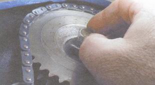 16. Slide the sprocket and chain onto the roller by pulling the driving chain leg and tighten the mounting bolt without tightening it.
 17. From above, hook the chain with a wire hook and ...
 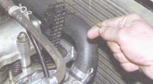 18. ... lift it up to the camshaft.
 19. Slide the chain over the camshaft sprocket and the sprocket onto the shaft, ensuring that the markings on the sprocket and bearing housing match up and tighten the drive chain.
20. Install the camshaft sprocket mounting bolt without tightening it.
21. Install the chain damper in the reverse order of removal.
22. Install the chain tensioner shoe in the reverse order of removal.
23. Install the tensioner in the reverse order of removal. Loosen the cap nut.
24. Install the stop pin in the reverse order of removal.
25. Disengage the gear, turn the crankshaft 2-3 turns in the direction of rotation.
26. Make sure the sprocket marks coincide with the engine marks. If the labels do not match, re-install the chain.
27. If the marks match, tighten the tensioner cap nut, engage the gear, tighten the sprocket bolts and lock them.
28. Install the removed parts in the reverse order of removal.
29. Check and, if necessary, correct the initial ignition moment
The standard VAZ 2106 timing belt serves for the correct direction of the air-fuel mixture into the cylinder system of the "six" engine and the exhaust of gases through the exhaust system. This occurs during the operation of systemically adjusted valves operating to open and close.
The main elements of the timing are a camshaft with a drive system, gears and valves. Because the timing mechanism is of the chain type, the chain requires interaction with other auxiliary systems - the timing chain tensioner and the damper. In addition, such a device involves making additional adjustments to the unit, such as tensioning the timing chain, using a damper of the right size, etc. In the case when the chain drive does not provide the functionality of the power plant, the VAZ 2106 timing chain is adjusted or replaced to restore the engine's working conditions.
Timing chain tension
Work progress:
- Dismantle the valve cover.
- We turn off the chain tensioner to the right of the unit on the cylinder head a few turns.
- Making rotational movements of the crankshaft vehicleturning it approximately 720 degrees, which should help tension the chain.
- In this case, the timing chain must take the required degree of tension. By pressing on the chain drive, we check the tension and tighten the tensioner itself.
- We mount all previously removed parts.
Replacing the timing chain
If the timing chain is replaced with a VAZ 2106, then the following set of tools will be required for the work: a set of locksmith tools, a special key "for 36", a fixing key for a universal pulley.
Work order:
1. Dismantle the housing part of the air purification filter.
2. Cover the open carburettor chambers with a rag so that no foreign matter falls into the manifold.
3. Dismantle the fuel line, unfasten the breaker cover and release the throttle cable.
4. Remove the valve cover and bottom crankcase protection.
5. Pour out the tasol from the radiator tank and slightly unscrew the adjustable upper mounting of the generator device.
6. Dismantle the cooling pipe, having previously loosened the fastening clamps.
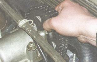
7. We release the radiator from the fasteners with the subsequent removal and dismantle the generator belt.
8. Using the special key on "36" we turn the crankshaft until the marks in the "pulley-cover" and "timing sprocket on the camshaft-tide bed of this product" pairs are aligned.
9. Dismantle the crankshaft pulley fasteners using a special key on "36", put a prepared stopper, which excludes the rotation of this part. In the absence of a stopper, turn on the 5th gear at the checkpoint and, depressing the brake pedal, dismantle it with a key.
10. We do the same with the camshaft drive casing.
11. Dismantle the timing chain tensioner fasteners and the product itself.
12. If the VAZ 2106 is equipped with an auto-tensioner, remove the timing sprocket fasteners, the product itself, mark the centering hole.
13. Dismantle the fuse, the auto-tensioner fasteners, as well as the so-called fasteners. "Piglet".
14. We dismantle the timing chain, the price of which is acceptable for the main group of motorists, as well as sprockets.
15. We test the installation of timing marks, while the crankshaft key should be against the tide on the engine block.
16. We carry out the installation of the chain on the previously mounted sprockets.
17. We attach the chain to keep it from slipping into the power unit.
18. Mount the camshaft sprocket so that opposite the clock hands are aligned with the chain marks.
19. Scrolling the camshaft at an acute angle and return by moving the crankshaft back. At the same time, we achieve chain tension and compare the position of the marks. If they do not coincide, we shift chain drive on the tooth and repeat the operation.
20. We put the chain tensioner and tighten its fasteners, followed by locking. We check: when the crankshaft rotates 720 degrees, the timing marks should match.
21. We carry out the installation of the timing belt in the case of installing a belt drive on such a "six" engine.
22. Assembly of all involved systems is carried out in the reverse order of the disassembly process.
Such a modern element of the "six" gas distribution mechanism, as a split timing gear, is designed for precise timing of the timing. After all, it is no secret that the accuracy of the phase settings of the gas distribution system is closely related to the dynamic characteristics of the power plant, as well as its efficiency with fuel consumption.
The peculiarity of installing such a component of the gas distribution system as a split gear is that all installation and adjustment work should be carried out with the cylinder head removed. This is due to the need for an extremely accurate setting of the TDC position. Otherwise, the adjustment of the chain, as well as the upper point, may be incorrect. It is very important to buy the right gear, taking into account the quality and price information.
